T Flip-Flop
The T (toggle) flip-flop has a single data input T. On each rising clock edge it inverts its stored output Q when T is 1 and keeps it unchanged when T is 0. Asynchronous PRE and CLR set or clear Q immediately (CLR wins). Because a stream of toggles naturally halves a frequency, the T flip-flop is the classic element for binary counters and clock dividers, and it is functionally a JK flip-flop with J and K tied together.
Toggling on every edge
Tie T high (to Power) and drive CLK from a Clock. Q now flips on every rising edge, producing a square wave at exactly half the clock frequency. Drop T to 0 and Q freezes at its current value. This single-input 'divide by two' is the most compact frequency divider you can build.
| CLK | T | Q(t+1) |
|---|---|---|
| rising | 0 | Q(t) (hold) |
| rising | 1 | Q'(t) (toggle) |
| no edge | X | Q(t) |
Excitation for a desired transition
To make Q change, assert T; to make it stay, deassert T. The excitation table therefore places a 1 exactly where the current and next states differ. This makes T flip-flops especially natural for counters, where each bit toggles precisely when all the lower bits are 1.
| Q(t) | Q(t+1) | T |
|---|---|---|
| 0 | 0 | 0 |
| 0 | 1 | 1 |
| 1 | 0 | 1 |
| 1 | 1 | 0 |
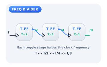
A ripple frequency divider
Chain three toggle flip-flops, each with T tied high, feeding the output of one into the clock of the next. The first stage divides the clock by two, the second by four, the third by eight. This is exactly how a hardware timer derives slow, human-scale ticks (seconds, tenths of a second) from a fast crystal oscillator.
Citations
- Eccles, W. H., & Jordan, F. W. (1919). A trigger relay utilising three-electrode thermionic vacuum tubes. Radio Review, 1(3), 143-146.. Reference 1
- Wakerly, J. F. (2018). Digital design: Principles and practices (5th ed.). Pearson.. Reference 2
- Shannon, C. E. (1938). A symbolic analysis of relay and switching circuits. Transactions of the American Institute of Electrical Engineers, 57(12), 713-723.. Reference 3