SR Flip-Flop
The SR (set-reset) flip-flop is the simplest clocked storage cell. On a rising clock edge S=1 sets Q to 1, R=1 resets Q to 0, and S=R=0 holds the previous value. The combination S=R=1 is forbidden because it asks the cell to be set and reset at once, leaving Q and Q' undefined. Asynchronous PRE and CLR act immediately (CLR wins). The SR flip-flop is the conceptual ancestor of all the others and maps directly onto the cross-coupled gate latch found inside real memory bits.
Set, reset and the forbidden state
Wire S and R to two switches and clock the flip-flop. Pulse S to latch Q=1, pulse R to latch Q=0, and leave both low to remember. Avoid asserting S and R together: the characteristic table marks that row as forbidden because the outputs are no longer complementary and the settled state is unpredictable.
| S | R | Q(t+1) |
|---|---|---|
| 0 | 0 | Q(t) (hold) |
| 0 | 1 | 0 (reset) |
| 1 | 0 | 1 (set) |
| 1 | 1 | forbidden |
Excitation table
To read the excitation table: to hold Q at 0 keep S=0 (R don't-care); to go 0 to 1 assert S and clear R; to go 1 to 0 clear S and assert R; to hold Q at 1 keep R=0 (S don't-care). The don't-cares show why SR logic can be compact, but the forbidden input still constrains the design, which is the trade-off the JK flip-flop resolves.
| Q(t) | Q(t+1) | S | R |
|---|---|---|---|
| 0 | 0 | 0 | X |
| 0 | 1 | 1 | 0 |
| 1 | 0 | 0 | 1 |
| 1 | 1 | X | 0 |
A one-bit storage / debounce cell
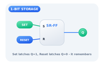
A single SR flip-flop is a complete one-bit memory: a Set button latches Q high and a Reset button latches it low, and Q holds between presses with no power to the buttons. The same set/reset structure is the heart of a switch debouncer, where the first clean edge from a bouncing contact sets the state and later bounces are ignored.
Citations
- Eccles, W. H., & Jordan, F. W. (1919). A trigger relay utilising three-electrode thermionic vacuum tubes. Radio Review, 1(3), 143-146.. Reference 1
- Mano, M. M., & Ciletti, M. D. (2018). Digital design: With an introduction to the Verilog HDL, VHDL, and SystemVerilog (6th ed.). Pearson.. Reference 2
- Shannon, C. E. (1938). A symbolic analysis of relay and switching circuits. Transactions of the American Institute of Electrical Engineers, 57(12), 713-723.. Reference 3