SIPO Shift Register
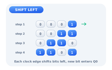
A SIPO (serial-in, parallel-out) shift register accepts one bit at a time on its serial DATA input and shifts the stored word left on every rising clock edge, so the newest bit enters position Q0 and older bits move up toward Q(N-1). After N clocks the whole word is available in parallel on the N Q outputs. An asynchronous Reset clears the register to 0. SIPO registers turn a single serial line into a parallel word, the receiving half of serial-to-parallel conversion.
Serial in, parallel out
Drive DATA from a switch, CLK from a Clock, and place an LED on each Q output. Set DATA and pulse the clock: the bit you fed in lights Q0, and on the next clock it moves to Q1 while a fresh bit enters Q0. After a few clocks the LED row shows the serial stream spread out in parallel. Pulse Reset to blank the whole register.
| Clock | DATA | Q3 Q2 Q1 Q0 |
|---|---|---|
| reset | - | 0 0 0 0 |
| 1 | 1 | 0 0 0 1 |
| 2 | 0 | 0 0 1 0 |
| 3 | 1 | 0 1 0 1 |
| 4 | 1 | 1 0 1 1 |
Watching the bits shift
Each rising edge performs value = (value << 1) | DATA, masked to N bits. So the register behaves like a moving window onto the last N serial bits. Feed a known pattern and you can watch it march across the outputs one position per clock, which is exactly how a receiver reassembles a byte arriving bit by bit.
A ring counter
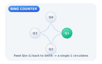
Feed the last output Q(N-1) back into the DATA input and preload a single 1. That lone bit now circulates around the register, one step per clock, so exactly one output is high at a time in an endless rotating pattern. This ring counter is a compact one-hot sequencer, perfect for driving stepper-motor phases, scanning a keypad, or lighting LEDs in a chase.
Citations
- Maity, H., Banerjee, S., Biswas, A., Pal, A., & Bhattacharjee, A. K. (2020). Design of reversible shift register using reduced number of logic gates. Micro and Nanosystems, 12(1), 42-48.. Reference 1
- Wakerly, J. F. (2018). Digital design: Principles and practices (5th ed.). Pearson.. Reference 2