JK Flip-Flop
The JK flip-flop is the most versatile of the clocked flip-flops. On each rising clock edge its two inputs select one of four actions: J=0 K=0 holds, J=1 K=0 sets Q to 1, J=0 K=1 resets Q to 0, and J=1 K=1 toggles Q. It removes the forbidden state of the SR flip-flop by redefining that combination as a useful toggle. Asynchronous PRE and CLR override the clock (CLR wins). Any other flip-flop can be built from a JK, which is why it is a favourite teaching and counter-design primitive.
The four JK modes
Drive J and K from two switches and CLK from a Clock. Try each combination and watch Q on the next edge: hold, set, reset, toggle. The characteristic table below captures all four behaviours in terms of the next state Q(t+1). Notice that J=1 K=1 gives the same divide-by-two toggle you would get from a T flip-flop.
| J | K | Q(t+1) |
|---|---|---|
| 0 | 0 | Q(t) (hold) |
| 0 | 1 | 0 (reset) |
| 1 | 0 | 1 (set) |
| 1 | 1 | Q'(t) (toggle) |
Excitation with don't-cares
The JK excitation table is rich in don't-care (X) entries: to move Q from 0 to 1 you only need J=1 and K can be anything, and so on. Those don't-cares give the logic minimiser more freedom, which is precisely why JK-based counters and state machines often need fewer gates than D-based ones.
| Q(t) | Q(t+1) | J | K |
|---|---|---|---|
| 0 | 0 | 0 | X |
| 0 | 1 | 1 | X |
| 1 | 0 | X | 1 |
| 1 | 1 | X | 0 |
A synchronous counter
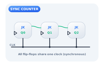
Give every JK flip-flop the same clock and use AND gates so that stage n toggles only when all lower stages are 1. Because all bits are clocked together, they change on the same edge with no ripple delay, giving a clean, fast count. This synchronous-counter pattern, built from JK primitives, is the template behind catalog parts like the 74LS163.
Citations
- Eccles, W. H., & Jordan, F. W. (1919). A trigger relay utilising three-electrode thermionic vacuum tubes. Radio Review, 1(3), 143-146.. Reference 1
- Katz, R. H., & Borriello, G. (2005). Contemporary logic design (2nd ed.). Pearson Prentice Hall.. Reference 2
- Shannon, C. E. (1938). A symbolic analysis of relay and switching circuits. Transactions of the American Institute of Electrical Engineers, 57(12), 713-723.. Reference 3