D Flip-Flop
The D (data) flip-flop is the workhorse memory element of synchronous digital design. On every rising edge of the clock it samples the D input and stores it in the output Q, holding that value until the next edge. Asynchronous PRE (preset) and CLR (clear) inputs force Q to 1 or 0 immediately regardless of the clock, with CLR winning if both are asserted. Because it captures data only at a well-defined instant, the D flip-flop is the standard building block for registers, pipelines and finite state machines.
Capturing a bit on the clock edge
Wire a Switch to D and a Clock to CLK, then place an LED on Q. Whatever level D holds at the instant of the rising edge is copied to Q and stays there for the whole clock period, even if you change the switch afterwards. This 'sample and hold' behaviour is what turns a combinational value into stored state.
| CLK | D | Q(t+1) |
|---|---|---|
| rising | 0 | 0 |
| rising | 1 | 1 |
| no edge | X | Q(t) (hold) |
Reading the excitation table
The excitation table answers the design question in reverse: given the transition you want Q to make, what must D be? For the D flip-flop it is trivial, D always equals the desired next state, which is exactly why D flip-flops are so convenient for state machines. Use PRE and CLR only for asynchronous power-on initialisation, never as part of the normal clocked datapath.
| Q(t) | Q(t+1) | D |
|---|---|---|
| 0 | 0 | 0 |
| 0 | 1 | 1 |
| 1 | 0 | 0 |
| 1 | 1 | 1 |
Building a ripple counter
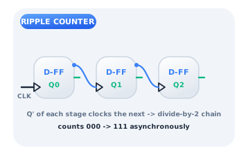
Connect each flip-flop's Q' (inverted output) back to its own D and route Q' to the clock of the next stage. Each stage then toggles at half the rate of the one before it, so a chain of D flip-flops counts in binary. This 'ripple' or asynchronous counter is simple but the stages settle one after another; when you need every bit to change at the same instant, switch to a synchronous counter that shares one common clock.
Citations
- Eccles, W. H., & Jordan, F. W. (1919). A trigger relay utilising three-electrode thermionic vacuum tubes. Radio Review, 1(3), 143-146.. Reference 1
- Shannon, C. E. (1938). A symbolic analysis of relay and switching circuits. Transactions of the American Institute of Electrical Engineers, 57(12), 713-723.. Reference 2
- Mano, M. M., & Ciletti, M. D. (2018). Digital design: With an introduction to the Verilog HDL, VHDL, and SystemVerilog (6th ed.). Pearson.. Reference 3