Output Terminal
A read-only probe that displays the value present on the wire or bus feeding it. It never drives a signal of its own; it only reports whether its input is logic HIGH (1) or logic LOW (0), or the binary number carried by a multi-bit bus. Like an input, an output can be mapped to a package pin so the finished circuit exposes it as a named external result.
Reading a single bit
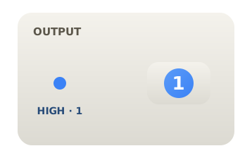
Wire any 1-bit signal into the output. It shows 1 when that signal is logic HIGH and 0 when it is logic LOW, updating live as the circuit runs. Because it only observes, connecting it never changes the value on the wire.
Displaying a 4-bit bus
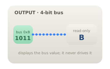
Raise the output's bit width to 4 and feed it a bus. It reads the whole bus as one binary number: the value 1011 appears as decimal 11 or hexadecimal B. This is the standard way to watch the result of an adder, counter, or arithmetic block without breaking the bus apart.
Naming an external result
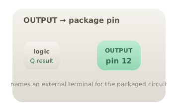
Map the output to a package pin and give it a label. When the circuit is packaged as a reusable subcircuit, that terminal becomes a named pin on the block's boundary, the counterpart of an input pin. This is how a designed module presents its computed results to the outside world.
Citations
- Mano, M. M., & Ciletti, M. D. (2018). Digital design: With an introduction to the Verilog HDL, VHDL, and SystemVerilog (6th ed.). Pearson. Reference 1
- Horowitz, P., & Hill, W. (2015). The art of electronics (3rd ed.). Cambridge University Press. Reference 2