LED (Light-Emitting Diode)
A single-bit luminous output. The LED lights up in its selected color when its input carries a digital 1 (HIGH) and stays dark on a 0 (LOW). It is the simplest way to visualize a logic signal on the canvas: wire any output to it and watch the level. In real hardware an LED is a semiconductor diode that emits light when current flows through it in the forward direction, so it only cares about the level on its single input, not about buses.
Switch driving an LED
Drop a Switch and an LED, then wire the switch output to the LED input. Toggle the switch: a 1 lights the LED, a 0 turns it off. This one-to-one mapping between a logic level and light is the whole idea behind the component.
| Input | LED |
|---|---|
| 0 | off |
| 1 | on |
Watching a gate output
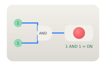
Feed two switches into an AND gate and connect the gate output to an LED. The LED lights only when both switches are 1, giving you an instant visual truth table. Because the simulator supports fan-out, you can tap the same gate output with several LEDs to probe it at multiple points.
Binary counter on an LED bar
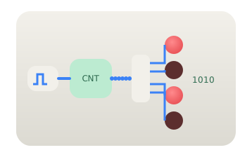
Drive a 4-bit Counter from a Clock, split its bus with a Splitter into four 1-bit lines, and light one LED per bit. As the counter advances 0000 to 1111 the LED bar shows the value in binary, the classic 'running lights' pattern. Since each LED reads a single bit, the Splitter is what turns the bus into individual signals the LEDs can display.
Citations
- Holonyak, N., Jr., & Bevacqua, S. F. (1962). Coherent (visible) light emission from Ga(As₁₋ₓPₓ) junctions. Applied Physics Letters, 1(4), 82–83. Reference 1
- Mano, M. M., & Ciletti, M. D. (2018). Digital design: With an introduction to the Verilog HDL, VHDL, and SystemVerilog (6th ed.). Pearson.