Input Source
A user-driven signal source. Each bit is an independent switch you toggle by hand: a bit set to 1 drives its wire to logic HIGH, a bit set to 0 drives it to logic LOW. With a bit width above 1 the terminals form a bus that carries a binary number, and the whole source can be mapped to a package pin so the finished circuit exposes it as an external input.
Driving a single wire HIGH
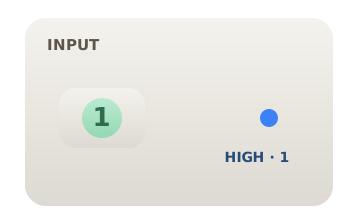
Set the input's single bit to 1. Its output terminal now holds logic HIGH (a steady 1) and anything wired to it reads that value. Click the bit again to return it to 0 and the wire falls to logic LOW.
A 4-bit input bus
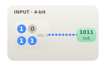
Raise the bit width to 4 and the source shows four independent switches, one per bit. Set them to 1, 0, 1, 1 and the bus carries the binary number 1011, which equals decimal 11 or hexadecimal B. The most significant bit is the leftmost switch. A single dotted bus wire carries all four bits at once to the rest of the circuit.
Pin mapping and driving logic
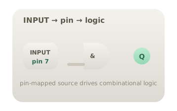
Assign the input to a package pin so that, when the circuit is reused as a subcircuit or exported, this source becomes a named external terminal instead of an internal control. Its output can fan out to many gates at once; every destination sees the same logic level, since a single source drives them all in parallel.
Citations
- Mano, M. M., & Ciletti, M. D. (2018). Digital design: With an introduction to the Verilog HDL, VHDL, and SystemVerilog (6th ed.). Pearson. Reference 1
- Horowitz, P., & Hill, W. (2015). The art of electronics (3rd ed.). Cambridge University Press. Reference 2