Counter
The counter is a ready-made synchronous up-counter. On each rising clock edge it increments its stored value and presents it on the Value bus; when the count reaches the Max Value input it wraps back to 0 on the next edge. An asynchronous Reset forces the count to 0 immediately, overriding the clock, and a Zero output flag goes high whenever the count is 0. It packages a whole chain of flip-flops and gates into one block, ideal for timing, addressing, event tallies and sequencing.
Counting clock pulses
Wire a Clock to the CLK input and read the Value bus on an Output or 7-segment display. Each rising edge advances the count by one. Press Reset (or pulse the Reset input) to jump straight back to 0 without waiting for a clock edge, that is what 'asynchronous' means here.

Wrapping at Max Value
Feed a Max Value to set the top of the range. A 3-bit counter with Max Value 5, for instance, walks 0-1-2-3-4-5 and then wraps to 0, giving a modulo-6 cycle useful for things like a 6-state sequencer. The Zero flag pulses once per cycle, which you can use as a carry into a second counter to extend the range.
| Edge | Count (Max=5) |
|---|---|
| 0 | 0 |
| 1 | 1 |
| 2 | 2 |
| 3 | 3 |
| 4 | 4 |
| 5 | 5 |
| 6 | 0 (wrap) |
A digital tally on a display
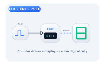
Chain Clock, Counter and a 7-segment display: the clock ticks, the counter increments, and the display shows a live running total in hexadecimal. Gate the clock with a Button through an AND gate and you have an event counter that only advances while pressed, the core of a stopwatch, a scoreboard or a production tally.
Citations
- Park, C.-M. (2010). A study on counter design using sequential systems based on synchronous techniques. Journal of Information and Communication Convergence Engineering, 8(4), 421-425.. Reference 1
- Mano, M. M., & Ciletti, M. D. (2018). Digital design: With an introduction to the Verilog HDL, VHDL, and SystemVerilog (6th ed.). Pearson.. Reference 2