Clock
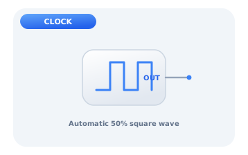
The clock is a free-running signal source that toggles its output automatically between 0 and 1 at a fixed period, producing a 50% duty-cycle square wave. It needs no inputs; you only set the period. The clock is the heartbeat of every synchronous circuit: its rising edges define the instants at which flip-flops, counters and shift registers update, so every sequential element you place will usually trace back to a clock.
A running square wave
Drop a Clock, wire its output to an LED and run the simulation: the LED blinks on and off at the configured period with no other input. Set the period in the properties panel, shorter periods blink faster. This same output is what you feed into the CLK pin of any flip-flop or counter.
Period and frequency
The period T is the time for one full high-low cycle; the frequency is simply f = 1/T. Halve the period and you double the frequency. In a simulator the period sets how fast the animation ticks, but the concept is identical to real hardware, where a crystal fixes T to a few nanoseconds. The table relates a few periods to their frequencies.
| Period T | Frequency f = 1/T |
|---|---|
| 1000 ms | 1 Hz |
| 500 ms | 2 Hz |
| 250 ms | 4 Hz |
| 100 ms | 10 Hz |
A clock-driven frequency divider
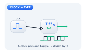
Feed the clock into a T flip-flop whose T input is tied high. The flip-flop toggles on every rising edge, so its Q output is a clean square wave at exactly half the clock frequency, a divide-by-two. Cascade more toggle stages to divide by 4, 8, 16 and derive many slower timing signals from one fast source, the basis of every digital timer and real-time counter.
Citations
- Rathore, T. S. (1984). A versatile astable multivibrator. IEEE Transactions on Industrial Electronics, IE-31(2), 157-158.. Reference 1
- Wakerly, J. F. (2018). Digital design: Principles and practices (5th ed.). Pearson.. Reference 2