How to wire two components
A wire carries a signal from one component's output port to another's input port. You draw one by dragging from an output to an input; when the pointer reaches a compatible port the wire snaps into place. Once connected, the wire is colored by the value it carries: green means logic HIGH (1), a dark line means logic LOW (0), and red marks a floating wire that is driven by nothing.
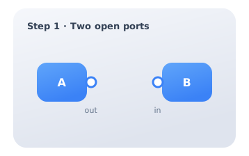
Step 1 — Two open ports
Place the two components you want to link. Every component exposes ports: small circles on its edges. An output port (on the right of source A) emits a signal; an input port (on the left of target B) receives one. Before wiring, both sit open and no signal flows between them.
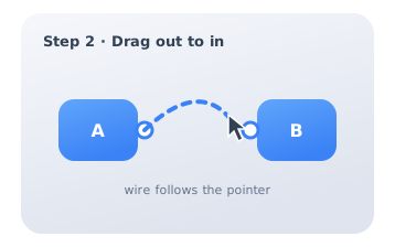
Step 2 — Drag from output to input
Press on the output port of A and drag toward the input port of B. A provisional wire follows the pointer as you move. Aim for the destination port; the editor highlights it when you are close enough for the connection to be valid. Release the pointer over the input port to drop the wire.
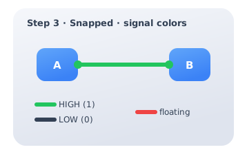
Step 3 — It snaps, and colors show the value
The wire snaps onto both ports and the signal now flows. Its color reports the live value: green is logic HIGH (1), a dark line is logic LOW (0), and red warns of a floating wire — one connected at an input but driven by no output. If you see red, trace it back to a missing source. Delete a wire by selecting it and pressing Delete.