XOR gate (exclusive OR)
The XOR gate outputs 1 when its inputs differ and 0 when they are equal; with more inputs it outputs 1 for an odd number of 1s. It computes A ⊕ B and is the heart of adders, parity checkers, and comparators.
Two-input XOR
Wire inputs A and B and read Y. The output is 1 in the two middle rows, where the inputs differ, and 0 in the rows where they match. XOR is the 'difference detector'.
| A | B | Y |
|---|---|---|
| 0 | 0 | 0 |
| 0 | 1 | 1 |
| 1 | 0 | 1 |
| 1 | 1 | 0 |
Controlled inverter
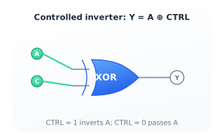
Feed data A into one XOR input and a control signal CTRL into the other. When CTRL is 0 the output equals A; when CTRL is 1 the output is Ā. A single XOR thus works as a switchable inverter — the basis of adder/subtractor selection and Gray-code conversion.
Half-adder
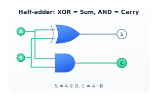
An XOR gate and an AND gate sharing the same two inputs form a half-adder: the XOR produces the Sum bit (A ⊕ B) and the AND produces the Carry bit (A · B). Chaining half-adders with an OR builds full adders and, from there, every binary arithmetic unit.
Citations
- Shannon, C. E. (1938). A symbolic analysis of relay and switching circuits. Reference 1
- Mano, M. M., & Ciletti, M. D. (2018). Digital design: With an introduction to the Verilog HDL, VHDL, and SystemVerilog (6th ed.). Reference 2