OR gate
The OR gate outputs 1 when at least one input is 1, and 0 only when every input is 0. It implements logical disjunction (A + B) and is used for combining conditions, alarms, and any 'at least one' decision.
Two-input OR
Wire inputs A and B and read Y. The output is 0 only in the first row, where both inputs are 0; any 1 on an input drives Y to 1.
| A | B | Y |
|---|---|---|
| 0 | 0 | 0 |
| 0 | 1 | 1 |
| 1 | 0 | 1 |
| 1 | 1 | 1 |
Alarm from two sensors
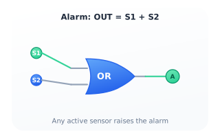
Connect two sensors S1 and S2 to an OR gate that drives an alarm lamp. If either sensor becomes active the alarm turns on; it stays off only when both sensors are quiet. This is the canonical 'any-of' condition.
OR of three signals
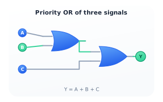
OR is associative, so A + B + C is built by cascading two two-input OR gates. The output is 1 whenever any of the three inputs is 1, and 0 only when all three are 0 — useful for collecting interrupt or fault lines onto a single flag.
Citations
- Boole, G. (1854). An investigation of the laws of thought, on which are founded the mathematical theories of logic and probabilities. Reference 1
- Shannon, C. E. (1938). A symbolic analysis of relay and switching circuits. Reference 2