Parity generator
A parity generator computes a single check bit from an input bus by XORing all of its bits. For even parity the bit makes the total number of ones even; for odd parity it makes the total odd. Appended to the data, this bit lets a receiver detect any single-bit corruption.
Even parity of 3 bits
The even parity bit is the XOR of all data bits. Input 101 has two ones, an even count, so P is 0; a single one makes P become 1 to keep the total even.
| b2 | b1 | b0 | P (even) |
|---|---|---|---|
| 0 | 0 | 0 | 0 |
| 0 | 0 | 1 | 1 |
| 0 | 1 | 0 | 1 |
| 0 | 1 | 1 | 0 |
| 1 | 0 | 0 | 1 |
| 1 | 0 | 1 | 0 |
| 1 | 1 | 0 | 0 |
| 1 | 1 | 1 | 1 |
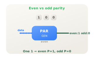
Even versus odd parity
The parity mode inverts the check bit. For input 100 (one set bit) even parity outputs 1 while odd parity outputs 0. Odd parity has the practical advantage that the all-zero word still produces a 1, so a fully dead line is detectable.
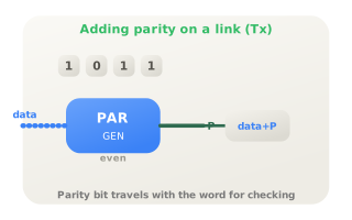
Attaching parity on transmit
On a serial or memory link the generator appends its parity bit to every word before it is sent or stored. UART frames, older ASCII channels and parity DRAM all carry this extra bit so the receiver can verify the word, following Hamming's error-detection principle.
Citations
- Hamming, R. W. (1950). Error detecting and error correcting codes. Reference 1
- Texas Instruments (2003). CD74HC280: 9-bit odd/even parity generator/checker [Data sheet]. Reference 2
- Mano, M. M., & Ciletti, M. D. (2018). Digital design: With an introduction to the Verilog HDL, VHDL, and SystemVerilog (6th ed.). Pearson.