Multiplexer (MUX)
A multiplexer routes one of several data inputs to a single output. The binary value on the select lines addresses which input is connected, so a MUX with n select lines chooses among 2^n data inputs. It is the fundamental data-steering and data-selection building block of digital systems.
2-to-1 multiplexer
With a single select line S, the output Y equals I0 when S=0 and I1 when S=1. The MUX simply picks which of the two inputs reaches the output.
| S | Y |
|---|---|
| 0 | I0 |
| 1 | I1 |
4-to-1 multiplexer
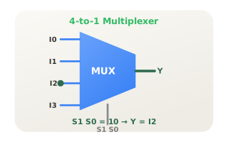
Two select lines S1 S0 address four data inputs. The pair 10 selects I2. Cascading select bits lets one MUX scale to 8, 16 or more inputs without changing the concept.
MUX as a function generator
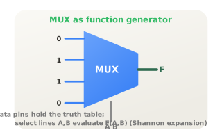
Any n-variable Boolean function can be implemented by a 2^n-to-1 MUX: wire the variables to the select lines and tie each data input to the constant 0 or 1 from the truth table. This is a direct hardware form of Shannon's expansion, turning a lookup table into logic.
Citations
- Shannon, C. E. (1938). A symbolic analysis of relay and switching circuits. Reference 1
- Texas Instruments (2004). SN74HC151: 8-line to 1-line data selectors/multiplexers [Data sheet]. Reference 2
- Mano, M. M., & Ciletti, M. D. (2018). Digital design: With an introduction to the Verilog HDL, VHDL, and SystemVerilog (6th ed.). Pearson.