Line decoder
A decoder drives exactly one of its output lines high, selected by the binary value on its input. An n-bit input activates one of 2^n outputs, producing a one-hot pattern. Decoders translate compact binary codes into individual control lines and are the counterpart of encoders.
2-to-4 line decoder
A 2-bit input selects one of four outputs. Only the addressed line is high while the others stay low, a one-hot code. Input 10 raises Y2 alone.
| A1 | A0 | Y3 | Y2 | Y1 | Y0 |
|---|---|---|---|---|---|
| 0 | 0 | 0 | 0 | 0 | 1 |
| 0 | 1 | 0 | 0 | 1 | 0 |
| 1 | 0 | 0 | 1 | 0 | 0 |
| 1 | 1 | 1 | 0 | 0 | 0 |
3-to-8 line decoder
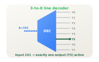
Three input bits address eight outputs. Code 101 activates exactly Y5. With an enable input the decoder doubles as a 1-to-8 demultiplexer, and each output is a minterm of the input variables.
Memory address decoding
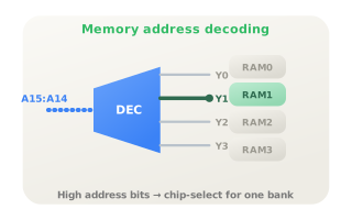
In a memory system the high address bits feed a decoder whose outputs are the chip-select lines: each code enables exactly one RAM or ROM bank while the low address bits pick the cell inside it. Because every output is a minterm, decoders also build arbitrary logic functions with OR gates.
Citations
- Shannon, C. E. (1938). A symbolic analysis of relay and switching circuits. Reference 1
- Texas Instruments (2003). SN74HC138: 3-line to 8-line decoders/demultiplexers [Data sheet]. Reference 2
- Mano, M. M., & Ciletti, M. D. (2018). Digital design: With an introduction to the Verilog HDL, VHDL, and SystemVerilog (6th ed.). Pearson.