Region Annotation
The Region annotation is a dashed rectangle used to group and highlight an area of the circuit. Like the other annotations it carries no signal and takes no part in simulation. You size it with its width and height and tint it with the 24-color design palette. By drawing a visible boundary around a set of components, a region exploits the way our perception groups things enclosed by a common border, making functional blocks instantly recognizable.
Boxing a functional block
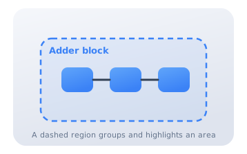
Draw a Region around a group of gates and label it (for example "Adder block") with a Text annotation. The dashed outline tells the reader that everything inside belongs together, even though the region itself does nothing electrically. It is the quickest way to carve a large schematic into digestible pieces.
Color-coded functional areas
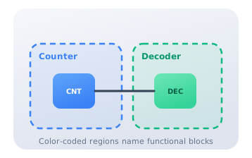
Give each subsystem its own tinted Region: a blue box for the counter, a green box for the decoder. The consistent colors act as a legend, letting a reader tell the parts of the machine apart before reading a single label. Grouping by a shared enclosure and a shared color are two independent perceptual cues that reinforce each other.
Nested regions for a datapath
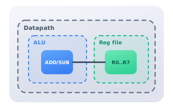
Nest Regions to show a hierarchy: an outer "Datapath" region containing inner "ALU" and "Reg file" regions. The containment relationship communicates that the inner blocks are parts of the outer whole, mirroring the block hierarchy of the design itself. This spatial nesting lets a reader zoom their attention from the whole machine down to a single unit without any accompanying text, which is why enclosure is one of the strongest grouping cues available to a diagram.
Citations
- Moody, D. L. (2009). The "physics" of notations: Toward a scientific basis for constructing visual notations in software engineering. IEEE Transactions on Software Engineering, 35(6), 756-779. Reference 1
- Koffka, K. (1935). Principles of Gestalt psychology. Harcourt, Brace and Company. Reference 2