Image Annotation
The Image annotation places a picture on the canvas purely for documentation. It has no input or output terminals and takes no part in simulation, so it never affects logic values or timing. Use it to embed a datasheet excerpt, a pin-out, a reference photo or a project logo next to the circuitry it explains. Like all annotations, it is a visual aid whose only job is to make the diagram easier to read and understand.
Dropping an image on the canvas
Place the Image annotation anywhere on the canvas and resize it with its width and height properties. Nothing wires to it and nothing reads from it: it is inert during simulation. Think of it as a sticker on your schematic rather than a component.
Documenting with a reference picture
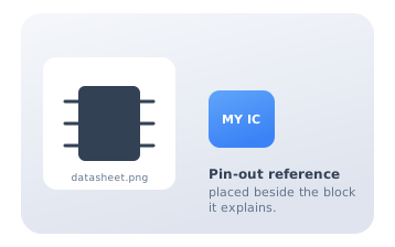
Place a datasheet pin-out or reference image right next to the block it describes. A reader can then compare your circuit against the source without leaving the canvas. Pairing a visual reference with the logic it documents reduces the mental effort needed to understand the design, which is exactly what good technical documentation aims for.
A title block for the whole sheet
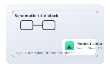
Combine an Image (a logo) with Text annotations to build a schematic title block: project name, revision, sheet number and author. This mirrors the title block found on professional engineering drawings and gives every exported diagram a consistent, self-identifying frame. Because annotations carry no signal, you can layer as many as you like without any risk to the simulation.
Citations
- Moody, D. L. (2009). The "physics" of notations: Toward a scientific basis for constructing visual notations in software engineering. IEEE Transactions on Software Engineering, 35(6), 756-779. Reference 1
- Tufte, E. R. (2001). The visual display of quantitative information (2nd ed.). Graphics Press. Reference 2